When working with bright objects in images we run the risk to clip signal while processing, or the signal might already be clipped to begin with. For big features that are really bright we can take images at different exposure times and use HDR processing to make sure we have all the information there and a good looking final image.
However, sometimes we might not realise this happening or it is just some small features. To me, this happens a lot whenever there ‘happens to be’ a planetary nebula in the FOV. They are not the main target and I might discover them only when working on the images. They are often bright though, so bright they can easily clip, especially if you are using Ha together with RGB. In this situation there is a solution though: it might be clipped in the Ha data, but surely the RGB data has non-clipped signal there!
This was the case with an image I’m currently working on and I want to share the way I used the RGB data to fill in the clipped signal in my HaRGB combined image.
But this will also be applicable to just RGB data. In many cases you are clipping signal during processing and you can easily make an alternate version of your data specifically targeting the previously clipped area. You can then use the data from the alternate version to fill in the clipped area in your ‘main version’ of your image.
Find the clipped signal
![]()
The Readout will tell you the values for the pixels and you can just go with your mousepointer to the object and see if it says 1.0 in any of the channels. In this case you’ll have 1.0 for R of course.
We can use Pixelmath to show us clearly where in the image we can find clipped signal. This will most likely also contain some stars. So for this I split the HaRGB image in the seperate color channels and use the following formula:
iif(HaRGB_R =>0.999,HaRGB_R,0)
And let it return a greyscale image. Now you have clearly visible where the pixels are you might want to target.
So why are we using 0.999 as a value instead of 1.0? This has to do with the fact that we start counting at 0 and this is the first value. Therefor we can never reach 1 because we are limited by the amount of values we can store. (compare it to counting to 10 on your 10 fingers, but starting at 0 😉 )
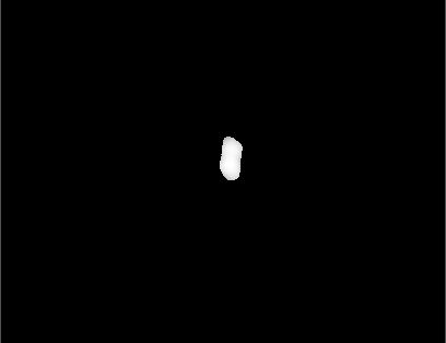
In my case this was the result for the area I’m interested in:
Create clipped signal mask
Now we can use this image to use as a mask to target only the pixels we want. You can use the CloneStamp tool if you have any structure or pixels in there you don’t want to replace. In order to get a good result however, we can’t use the image just like it was returned from PixelMath as it has really sharp edges wich will result in ugly transitions.
So to smoothen the edges we use Convolution with some high settings and smoothen the mask.
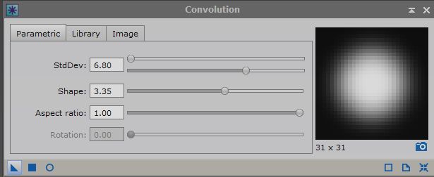
For me this was the result:

Much better!
If you need more control over the blur however, you could also use PixelMath and create multiple masks for different pixel values. You can then combine those masks with different strengths to create your own smooth transition.
For instance; create a mask1 for pixel values above 0.9999, mask2 for pixel values above 0.9995, mask3 for pixel values above 0.999, etc.
Then combine those masks with different strenghts in PixelMath by simply adding them together with different multiplications like;
1*mask1+0.8*mask2+0.6*mask3 etc.
Replace clipped signal with RGB data
Now we can simply use the mask on the main image and use PixelMath to copy over the non-clipped signal. To do this you need to apply the mask you just created to the main image.
Then open PixelMath and simply type in the name of the image that contains the non-clipped signal you want to copy over. Make sure you checked ‘Replace target image’ since masks don’t work when you use Create new image. Now drag the New instance icon (the little triangle in the bottom left corner) over on the main image and you’re done!
To tweak the results a bit you can experiment with turning up the signal you copy over a bit by simply using a multiplication in PixelMath. So instead of just using the image name you can put in
RGB*1.2
to strengthen the signal a bit.
The result
In my case this was the result.
![]()
Eventhough it’s just a tiny area of 60 by 90 pixels in an image of 11308×7880 pixels, I do think paying attention to the little details like this is worth it. Especially if it’s in areas of high significance in terms of objects 😉
A special thanks to Niall Saunders who helped me out with this on the PixInsight forums.
